All of the basic shapes, as well as anything created with the pencil or line tool, can be considered to be a path. A path is a series of points and segments between those points. Any two points can either be disconnected (no line between them), connected with a straight line segment, or connected with a Bézier curve.
Bézier Curves
A Bézier curve, also sometimes called a quadratic curve, is a type of curve used in vector graphics that connects two points. A Bézier curve is configured using four points: the two end-points and two control points. The curve starts along the line between the an endpoint and the first control point, and then curves to smoothly meet the line between the second control point and the other endpoint.
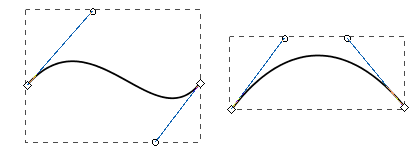
Examples of Bézier curves
Editing Paths Directly
Editing paths is done using the path tool (![]() ). Simply select any shape or line while the path tool is active to start editing it. If the shape is already a path, you can also switch to the path tool by double-clicking on the shape. You can convert any shape into a general path by selecting the To Path (
). Simply select any shape or line while the path tool is active to start editing it. If the shape is already a path, you can also switch to the path tool by double-clicking on the shape. You can convert any shape into a general path by selecting the To Path (![]() ) function under the Shape menu. Shapes will also implicitly be turned into paths if they are altered in a way not supported by the underlying shape. For example, if you stretch a rotated rectangle, thereby skewing it into a parallelogram, it will become a path automatically.
) function under the Shape menu. Shapes will also implicitly be turned into paths if they are altered in a way not supported by the underlying shape. For example, if you stretch a rotated rectangle, thereby skewing it into a parallelogram, it will become a path automatically.
Each point on the path is represented by a diamond-shaped handle when the path editor is active. These handles can be dragged to move them around. They can also be selected by clicking on them or dragging a selection rectangle to select multiple points. This allows groups of points to be altered simultaneously. Bézier segments also have handles on their control points, represented by small circles with a line drawn back to an endpoint that can be dragged to change the curvature of the segment.
To change a segment between open, straight, and curved, simply use the toolbar functions that become visible when the path editor tool is active. Points can also be added and removed using the functions on the path editor toolbar. Filled shapes have two fill settings that control whether or not holes in the shape should be filled. To remove the fill entirely, simply set the fill paint property to "No Paint".
Tip! When editing paths directly, it is often useful to be zoomed in on the path. Don't forget that you can zoom in on a location by holding down ctrl and using your mouse wheel to zoom in on a particular area without having to zoom in and then scroll. Also, if you press your mouse wheel in, you can pan around your window.
Creating and Editing Shapes Using Constructive Area Geometry
Editing paths directly can be a bit awkward. Using Constrictive Area Geometry is usually a much easier and more intuitive to get the shape that you want. These functions are accessed from the Shape menu and operate when two (or more) shapes are selected. Note that the order that you select the shapes is important for many of these functions. Typically, the first shape you select is the shape you want to retain, and the second shape is the shape that you want to use as an "operator" on that first shape.
Union
The union function combines two or more paths into one. The resulting shape will cover the area that any of the shapes covered initially. The example shows how the union of a circle, rectangle, and triangle can be unioned together to create a basic pump symbol. Creating the symbol using this method took a few seconds, whereas attempting to draw this shape by hand using paths would be quite frustrating.
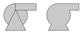
Union: combine basic shapes to make symbols
Difference
The difference function can be thought of as using one shape as a "hole-punch" to remove a section of another shape. The example shows how a zigzag shape drawn with the line tool can be used to punch a cutaway out of a basic tank shape. The level indicator is added behind the resulting shape to show how the area where the zigzag shape was is no longer part of the tank shape.
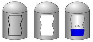
Difference: create cutaways and holes in shapes.
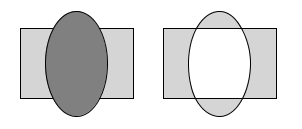
Intersection
The result of an intersection function will be the area only where where two shapes overlap. The example shows how the "top" of the tank in the difference example was easily made using two ellipses.
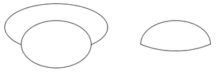
Intersection: where two shapes overlap
Exclusion
The exclusion function, sometimes called X-OR, creates a shape that occupies the area covered by exactly one of the source shapes, but not both.
Exclusion: XOR for shapes!
Division
The division function divides or cuts one shape up along the outline of another shape.
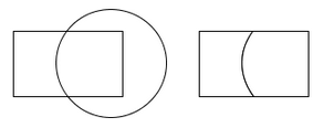
Division: cut up a shape using the outline of another.