Connections to ControlLogix, CompactLogix, PLC-5, MicroLogix and SLC Allen-Bradley processors through a ControlLogix Gateway require a connection path. The connection path is unique to your setup and is dependent on what modules the connection is being routed through. With there being nearly an endless number of ways to route your connection from device to device it is impossible to give an example of every possible connection path, but in general there is a pattern to how the connection path is specified.
Follow the Path
A connection path is exactly what it sounds like. It is a path that when followed will lead a processor residing in a numbered slot of a chassis somewhere on site. You merely have to follow the path and build the connection path as you go.
The first connection point between Ignition and the device is a ControlLogix Ethernet module such as an ENET, ENBT or EN2T module. The slot number of this module doesn't matter and there is no need to specify it in the connection path. The first entry in any connection path will be a 1, which specifies moving to the back plane. You then specify the slot of the module you wish to move to, followed by the port or channel of that module that you wish to exit through. Finally you specify the address of your entry point to the next module and the process starts all over again. This process may sound complicated at first but after some practice it will get easier.
Steps
| 1. | Move to the backplane |
| 2. | Specify the slot number of the module you are moving to |
| 3. | Specify the exit port or channel |
| 4. | Specify address of entry point (DH+ Station Number / ControlNet Address / IP Address of ethernet module) |
| 5. | Move to the backplane |
| 6. | Specify processor slot number OR the slot number of the module you wish to exit through |
Connection Path Entries for Different Module Types
How you specify your exit point from a module is slightly different depending on which module type you are using. You can only move in two directions once you are "in" a module: out to the back plane, or out through the module port/channel. Ethernet modules have ethernet ports and an IP address; ControlNet modules have ControlNet Ports and ControlNet addresses; DHRIO modules have channels and station numbers. Below is a list of different kinds of modules and what numbers you specify in the connection path when you are exiting or entering those modules. When in a module, an entry of 1 will always take you to the backplane.
ENET, ENBT, and EN2T:
Exiting
1 = Backplane
2 = Ethernet Port
Entering
IP Address
CNB:
Exiting
1 = Backplane
2 = ControlNet Port
Entering
ControlNet Address
DHRIO
Exiting
1 = Backplane
2 = DH+ Channel A
3 = DH+ Channel B
Entering
DH+ Station Number (an octal value between 0-77)
You use these numbers to specify how to move out of the module, then you specify where you are moving to by either specifying the DH+ station number, ControlNet address, or the IP address of another ethernet module. Your connection path will always be an even number of entries due to the fact that you always move in two steps: out of a module and then in to another module. So if your connection path ends up with an odd number of entries you have missed a step somewhere and you'll have to go back and trace the path again.
Some examples have been included to help illustrate the process of tracing a connection path. The first three examples illustrate how to build your connection path when going from one ControlLogix Gateway to another. The last example shows connecting through a ControlLogix Gateway to 3 different SLC 5/04 devices via DH+.
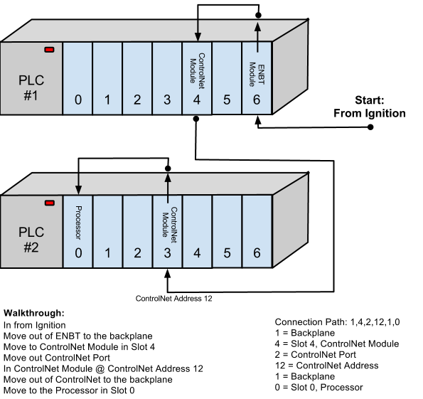
ControlNet Example
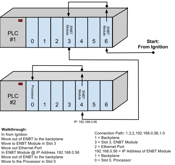
ENBT Example
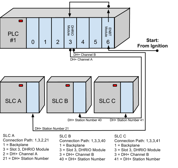
DHRIO Example

ControlLogix Gateway -> SLC using DH+