Modbus Specific Addressing
Per the Modbus protocol specification there are four basic types of addresses that can be read from a device. These include Holding Registers (read/write 16 bit words), Input Registers ( read only 16 bit words), Coils (read/write bits) and Discrete Inputs (read only bits associated with device input points).
Modbus Specific Addresses can be manually entered into the OPC Item Path of an OPC Tag using the following designators followed by the Modbus address.
HR for Holding Register
IR for Input Register
C for Coil
DI for Discrete Input
Because some devices that support Modbus protocol store data in BCD format, there are two additional designators. These designators will convert the data from BCD format to decimal when reading data from the device and convert data from decimal to BCD when writing to the device.
HRBCD for Holding Register with BCD conversion
HRBCD32 for 2 consecutive Holding Registers with BCD conversion
IRBCD for Input Register with BCD conversion
IRBCD32 for 2 consecutive Input Registers with BCD conversion
To accommodate other data encoding commonly used by Modbus supported devices, the following designators are available for Modbus specific addressing.
HRF for 2 consecutive Holding Register with Float conversion.
HRI for 2 consecutive Holding Register with 32 bit integer conversion.
HRUI for 2 consecutive Holding Register with 32 bit unsigned integer conversion.
HRUS for Holding Register with 16 bit unsigned integer conversion.
IRF for 2 consecutive Input Register with Float conversion.
IRI for 2 consecutive Input Register with 32 bit integer conversion.
IRUI for 2 consecutive Input Register with 32 bit unsigned integer conversion.
IRUS for Input Register with 16 bit unsigned integer conversion.
To read or write string values from/to a Modbus device, the following designation is available for Modbus specific addressing.
HRS read or write consecutive Holding Registers as a string value.
Note that there are 2 characters for each word and the order of which character comes first is controlled by the Reverse String Byte Order device setting as described above. Because two characters are stored in a word, the string length must be an even number of characters.
HRS FORMAT: HRS<Modbus address>:<length>
Examples:
[DL240]HR1024 Read 16bit integer value from Holding Register 1024.
[DL240]HRBCD1024 Read 16bit BCD value from Holding Register 1024.
[DL240]IR512 Read 16bit integer value from Input Register 512.
[DL240]C3072 Read bit value from Coil 3072.
[DL240]IR0 Read 16bit integer value from Input Register 0.
[DL240]HRS1024:20 Read 20 character string value starting at Holding Register 1024.
The Modbus unit ID can also be specified by prepending it to the Modbus address. For example, to access Modbus unit ID 3 and read HR1024 the full OPC path is [DL240]3.HR1024.
The Modbus specification does not support bit level addressing but it can be specified in the OPC Item Path. Please note that this only applies to reading bits of words and does not apply to writing bit values.
Example:
[DL240,bit=7]HR1024
Address Mapping
Because it can be very tedious manual entering OPC Tag information one-by-one, the driver has an address mapping feature. This allows entering blocks of common addresses and the driver will create the individual addresses and display them in the OPC browser.
Another benefit of address mapping is the addresses inside a device can have a different numbering scheme than the Modbus address. The Direct Automation DL240 is a perfect example of this. Address V2000, capable of holding a 16 bit integer, is Modbus Holding Register 1024. In addition, the DL240 addressing is in octal meaning there are no 8 or 9s. The sequence of addresses go: V2000, V2001, V2002, V2003, V2004, V2005, V2006, V2007, V2010, V2011.... V3777. This is not very straight forward.
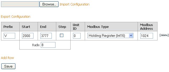
Below details how to map the DL240 address range V2000 to V3777 in octal to Modbus Holding Register addresses 1024 to 2047. Also, notice the Radix setting that in this example being equal to 8 causes the addresses to be in octal (also known as base 8).
Note that mappings for string data types cannot be entered. Strings can only be read or written using Modbus Specific Addressing. See above for more details.
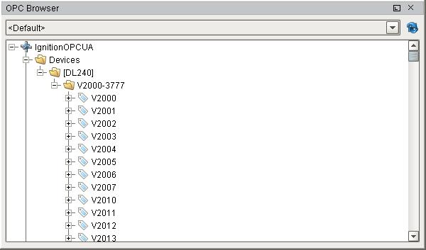
Once this mapping has been entered and saved, the OPC browser or the Quick Client will show all the DL240 addresses from V2000 to V3777 in octal.
Example
.jpg)
This shows mapping for all of the DL240 addressing.
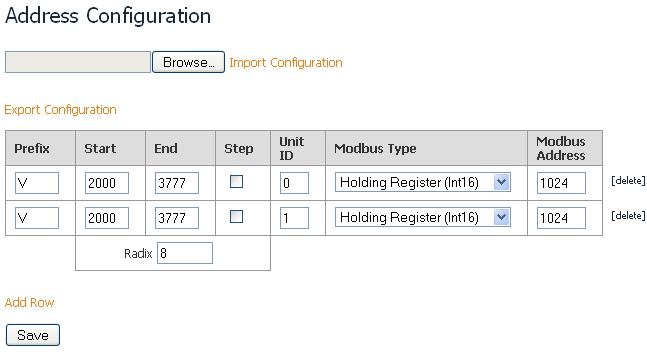
When communicating to multiple devices through a Modbus gateway where the gateway only has one IP address, it is not recommended to add multiple Modbus devices with the same IP address. Only one Modbus device should be added to the Ignition OPC-UA Server device list for the gateway and to specify the different unit IDs in teh address mapping. The unit ID is specified for each entry in the address mapping for the Modbus device. Notice in the example address mapping below, that the Prefix, Start, End, Modbus Type and Modbus Address can be the same for two entries provided that the Unit IDs are different.
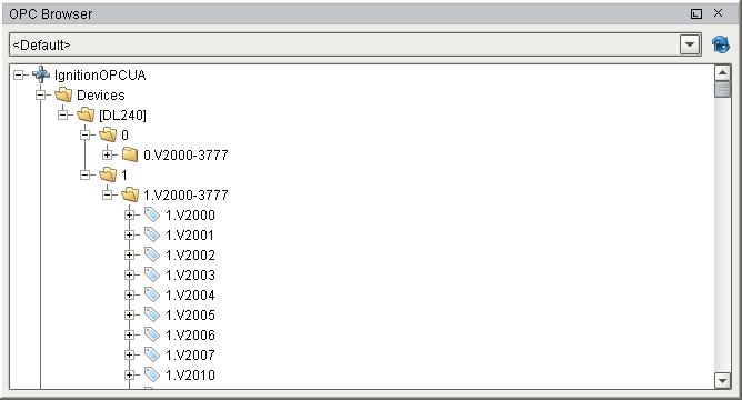
Now when browsing the Modbus device, the unit ID will show as a folder and The OPC tag path will include the unit ID as shown below. This only happens when more than one unit ID is specified in the address mapping else the unit ID will be eliminated.
Modbus doesn't support reading and writing to any other memory types other than bits and 16 bit words. This is not very useful when reading from or writing to float point or 32 bit integers. To get around this the Modbus driver has been designed to read 2 consecutive 16 bit words and encode it into the desired data type.
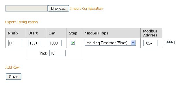
The Modbus address mapping below details how to map float point addresses starting at 1024 and ending at 1030. With the Step check box selected, the addresses on the Ignition side will be index by 2. In this case R1024, R1026, R1028 and R1030 will be created.
Because the Modbus Type of Holding Register (Float) is selected, the driver will read two consecutive 16 bit words and convert it to a floating point value. It will also index the Modbus Address by 2 for each entry. In this case, R1024 will read from Modbus addresses 1024 and 1025 and convert them into a floating point value. When writing, the reverse of converting a floating point value into two 16 bits words is done before sending them to the device.
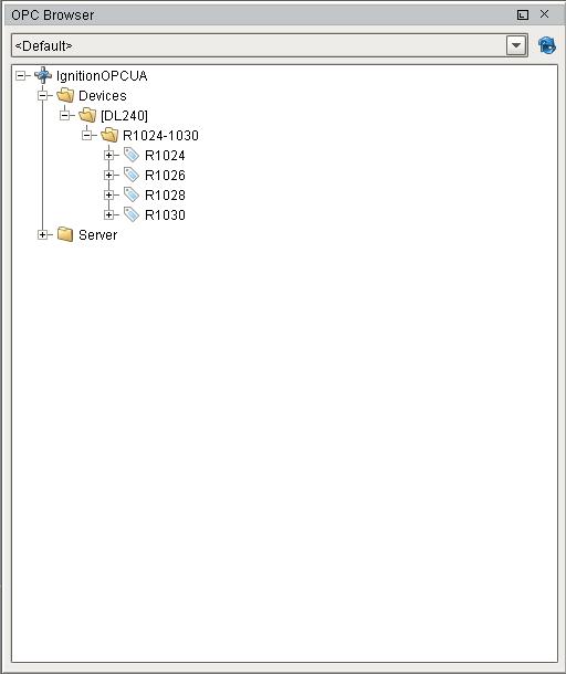
This shows what appears in the OPC Browser. Notice that the numbering is index by two and that it matches the Modbus address. With some devices, this will allow the addresses appearing in the OPC Browser to match the addresses in the device.
Import / Export Address Mapping
The mapping configuration can be exported to a comma separated values (csv) file. The csv file can later be imported in other Ignition installations or like devices.